In the article below, Softing’s Peter Subke helps navigate both the layers of the Open Systems Interconnection (OSI) model that apply when diagnostic testing, and the relevant automotive SAE standards that apply.
News
The Future of On-Board Diagnostics: OBD on UDS and ZEV on UDS
Figure 1 shows a classical communication system for diagnostic applications. The Vehicle Communication Interface (VCI) connects a Diagnostic Tester (TST), also referred to as a Scan Tool, with the Diagnostic Link Connector (DLC) of the vehicle. For diagnostic purposes, the TST sends diagnostic service requests to the vehicle and receives diagnostic service responses from the vehicle.
Requests and responses are specified in diagnostic communication protocols. Internationally standardized diagnostic communication protocols are based on the Open Systems Interconnection (OSI) Basic Reference Model, which structures communication systems into seven layers (Figure 2).
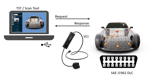
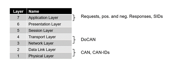
Figure 1: Classical communication system with VCI
Figure 2: The 7 Layers of the Open Systems Interconnection (OSI) Model
Requests and responses are specified on the Application Layer (L7) of the OSI model. Examples of L7-protocols include UDS on CAN and OBD on UDS, whereas UDS is short for Unified Diagnostic Services and OBD for On-Board Diagnostics. UDS is specified in ISO 14229-3, and OBD on UDS in SAE J1979-2 (Figure 3).
Figure 4 shows the 26 diagnostic services as they are specified in ISO 14229-1. Each request can be identified by a unique Service Identifier (SID) and is parameterized by a Data Identifier (DID) or a sub-function byte (marked with *). Examples of DIDs include 0xF1,90 for the Vehicle Identification Number (VIN) and 0xF4B2 for the State of Health (SOH) of a Zero Emission Vehicle (ZEV) propulsion system battery.
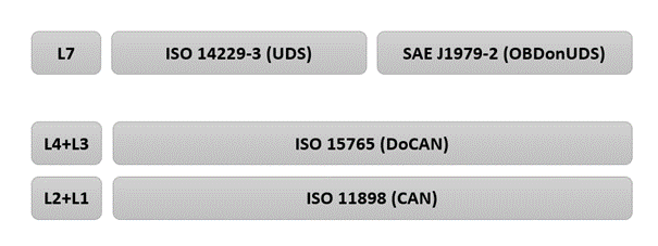
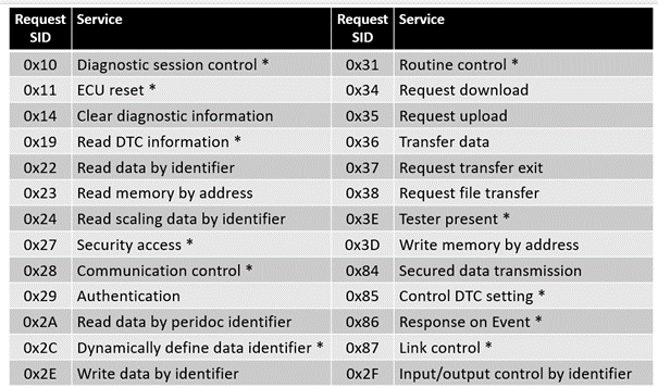
Figure 3: Diagnostic Communication mapped to the OSI model
Figure 4: ISO 14229 specifies 26 generic diagnostic services
Combustion to propulsion
On-board diagnostics (OBD) systems were originally devised to support the protection of the environment against harmful pollutants such as carbon monoxide (CO), nitrogen oxide (NOx), hydrocarbons (HC) and particulate matters (PM) emitted by combustion engines.
The Application layer protocol SAE J1979 and its “OBD Modes” on CAN served to protect our environment against harmful pollutants for decades, but due to regulatory adoption of Unified Diagnostic Services (UDS), SAE J1979 has now become a multiple part document series: SAE J1979 will be replaced by SAE J1979-2 for vehicles with combustion engines (ICEs) and by SAE J1979-3 for Zero Emission Vehicle (ZEV) propulsion systems. For ZEVs, emission-related failures will be replaced by ZEV propulsion-related failures.
SAE J1979-3 is not an explicit “OBD regulation” requiring specific failure monitoring. Rather, it is tied to regulations requiring diagnostic data and powertrain operation data standardization in support of ZEV serviceability, warranty compliance, promotion of ZEV second life sales market, and providing data necessary to confirm the vehicle´s compliance with battery durability requirements. We can assume that further ISO 14229 services, sub-functions and/or DIDs as well as ZEV-related DTCs will be included in new versions of SAE J1979-3 in the future.
Both SAE J1979-2 and -3 are variants of ISO 14229 (UDS) but limited to emission-related and ZEV propulsion-related failures, respectively, and associated diagnostic data. These new diagnostic communication protocols are required by California Air Resources Board (CARB). Implementation of SAE J1979-2 started in 2023 and is mandatory for all vehicles with a combustion engine by model year 2027. All zero Emission vehicles (ZEV) and Plug-In Hybrid Electric Vehicles (PHEV) must support SAE J1979-3 by model year 2027.
Neither J1979-2 or -3 support vehicle-manufacturer-specific diagnostic applications like calibration or flash programming. For performance reasons, UDS on Internet Protocol (UDSonIP) as standardized in ISO 14229-5 has become the state-of-the art for flash programming.
The classic diagnostic communication protocol, SAE J1979 is technically harmonized with ISO 15031, however the new parts (SAE J1979-2 and -3) are not. The good news is that the application layer protocols SAE J1979-2 (OBDonUDS) and SAE J1979-3 (ZEVonUDS) reference the same set of the lower Open Systems Interconnection (OSI) layer protocols all the way down from Layer 4 (L4) to Layer 1 (L1), meaning to DoCAN on CAN and to DoIP on Ethernet. The OSI-Model Application Layer of SAE J1979-2 is a derivate of ISO 14229-1, and the SAE J1979-3 is a subset of SAE J1979-2. The lower OSI-Model Layers are also specified in ISO standards. These include DoCAN (ISO 15765) on CAN (ISO 11898) and DoIP (ISO 13400) on Ethernet (IEEE 802.3).
Dipl.-Ing. Peter P. Subke

 linkedin
 twitter
 youtube
 youku
youku weixin