Developer Blog

13/09/2019 by Bryan Hennessy

An Introduction to J1939 and DBC files

This is an introductory guide to understanding and working with J1939 DBC files. 

Prerequisites:


Summary

The DBC file is an ASCII based translation file used to apply identifying names, scaling, offsets, and defining information, to data transmitted within a CAN frame. For any given CAN ID, a DBC file can identify some or all of the data within the CAN frame. The data in a CAN frame can be broken up into eight one-byte values, sixty-four one-bit values, one sixty-four bit value, or any combination of these, and a DBC file can be used to identify, scale, and offset the data represented by any or all of these values.


Introduction

Working with Controller Area Network (CAN) data is for the most part an exercise in understanding formats and translation. When working with CAN data, it’s never long before the subject of the DBC file is introduced, because this is the most common way to handle identification and translation of the data. Specifically, I’m referring to the identification of CAN messages and the translation of the raw CAN data, as transmitted within a CAN frame, to meaningful values and meaningful information.

The DBC file type was developed by Vector Informatik GmbH in the 1990s to provide a standard means of storing information described in a CAN network. Used by the automotive industry primarily, Vector database files (.dbc) have since become the de facto standard for exchanging CAN descriptions. Similar standards operate for other bus systems, such as FIBEX database files (.xml) for FlexRay and LDF for LIN (.ldf).

The SAE J1939 standard is written and maintained with a complete understanding of the DBC file, but the term and details are rarely mentioned by the standard. In fact, I recently scanned most of the SAE J1939 standards documents and neither the terms ‘DBC’ nor ‘database’, in the context of the DBC file, appeared in any of the documents.

DBC is short for ‘database’, and you hear engineers using the two names interchangeably. Although the word database is used in many other places and in many other contexts, when used in connection with CAN data, it’s probably referring to the DBC file.


The J1939 DBC file

If we limit the discussion to J1939 DBC files, it is important to understand that the SAE J1939 Standards Committee (formally named Truck Bus Control and Communications Network Committee) does not maintain or distribute a DBC file of any kind. The Standards Committee assigns many identifiers, names, numbers and formats that are represented in a DBC file, but the file itself is not a product of the SAE. SAE maintains and sells a Windows Excel file that is used to communicate the technical information needed to create a J1939 DBC file. This Excel file is called J1939DA, or Digital Annex, and can be purchased at the SAE web site here:

Once you have the Digital Annex, you can create a J1939 DBC file containing all or some of the information within it. If your product only needs to understand a few of the messages within the SAE J1939 standard, then your DBC file only needs to define the messages your product needs to understand, and all other messages do not need to be defined in your DBC file.

There are many Windows applications for the PC that will read a DBC file, including Kvaser’s CanKing, Vision and CANLab from Accurate Technologies, CANtrace from TK Engineering, MATLAB Vehicle Network Toolbox from Mathworks, PiSnoop from Pi Innovo, X-Analyser from Warwick Controls, CAN db++ from Vector, and many more. You can also read and edit a DBC file with Windows Notepad if you like, but this is difficult because the file is not easy to understand and uses special characters to do different things. One easy option for viewing and editing a DBC file is the free Kvaser Database Editor 3 available for download here:

There are many other suppliers who offer DBC file editors with different capabilities, whilst some Kvaser partners have embedded the Kvaser Database Editor into their tools.

Most PC based software applications allow for the use of more than one DBC file simultaneously. This is because a given CAN bus sometimes contains J1939 messages as well as other information not defined by J1939, including proprietary messages, other protocols and even calibration data. It’s common to have two or more DBC files associated with one CAN bus monitoring application in order to define the different data within that application. It’s also common to see messages on complicated CAN networks that are not defined by any of the associated DBC files, and in this case the messages will usually be displayed by the application as raw CAN data.


Legal Considerations

The SAE J1939DA, or Digital Annex, is considered by SAE to be their intellectual property, and therefore is protected by SAE Patents and/or Copyrights as appropriate. The first line of SAEs IP Statement is:

SAE’s intellectual property is its most valuable asset. As such, the Society expends considerable resources maintaining and protecting its rights to its intellectual property.

Since a J1939 DBC file is a digital representation of the information within the SAE J1939DA, the SAE considers a J1939 DBC file to be their intellectual property. I am not a lawyer, so I recommend you review the SAE Terms and Conditions with a lawyer before you resell anything that could be considered SAE Intellectual Property.

https://www.sae.org/about/legal-policies


Purchasing the J1939 Protocol Stack

Numerous Kvaser Technical Associates do sell the J1939 Protocol Stack for system development. For more information, including price, you can contact them directly

emotas GmbH (Germany)
Link: www.emotas.de/en/produkte/sae-j1939-stack
Email: service@emotas.de

LogiCAN (Israel)
Link: www.logi-can.com
Email: ranweiss@bezeqint.net

Warwick Control Technologies (UK)
Link: www.warwickcontrol.com/protocol-stacks/
Email: sales@warwickcontrol.com


Understanding the Data within a CAN frame

Before we can use the information within a DBC file as it was intended, we need to separate the CAN frame identifier from the data. This is an article directed at understanding the DBC file, so I’m not going to go into great details regarding the CAN frame, other than to show how to separate the identifier from the data. Here is an example of a typical CAN frame with a 29-bit identifier and eight bytes of data, as represented within CanKing:

a typical CAN frame with a 29-bit identifier and eight bytes of data, as represented within CANKing

I have highlighted each section of this CAN frame in order to distinguish different blocks of information, and I have labeled each of these blocks with a lower-case letter, a to g.

a – This is simply the channel in the device that the data was received on. A zero represents channel 1.

b – Message identifier. For those of you who want to understand more, the identifier contains the Priority, Parameter Group Number (PGN), and Source Address (SA) of the message.

c – The X is an indication that this is an extended identifier message, or a 29-bit identifier.

d – The Data Length Code (DLC) is 8, meaning this message includes eight bytes of data.

e – This is what we’re after, the eight bytes of data.

f – This is a time stamp in seconds, added by the application to each CAN frame received.

g – The R simply tells us that this frame was Received by CanKing.

Now that we have isolated the data portion of the CAN frame, we can start to understand how the data is represented. This is where we look to the DBC file. The DBC file provides the information needed for the application to understand the data, take the data apart, apply a scale and offset, label the data, and interpret it. This explanation is being presented from the point of view of receiving data. We do all these things when we receive CAN frames. If we were to apply this to the creation and transmission of CAN frames, we world just reverse our thinking and reverse the order of operations. This article will explain the DBC file as related to receiving CAN frames, because once you understand this, it’s not difficult to understand the transmission side.


Example of how a DBC file is used

If we were looking at a CAN trace with any given monitoring software, and a message within that trace was not defined by one of the associated DBC files, it would be shown as a raw CAN frame and would look something like this:

a raw CAN frame not defined by J1939 or other DBC

This is a line captured with Kvaser’s CanKing, a free CAN monitoring application that works with any Kvaser interface, and can be downloaded here:

CanKing uses what we call Formatters to format the data and make it more understandable to display.  You can choose from different formatters in CanKing, and this is done by opening the Select Formatter window.  The data above was formatted using the Standard Text Format option in CanKing.  I’m not going to go further into CanKing and its formatters because this article is about DBC files, but since we’re using CanKing to display data used in the examples in this article, it is important to mention the formatting options and a little about the different formats.

CanKing is capable of loading and using DBC files in order to make this data more meaningful and easier to read. If we go through the process of loading the appropriate DBC file into CanKing for this test, the identifier for this CAN frame will be recognized, and the appropriate translation and identifications will be applied to the data within the sequence. Your display would now look more like this:

0	18FE6900 X   	8  9C  27  DC  29  FF  FF  F3  23 	230.871160 R
CAN 1    65129   0 all 6                  J1939.ET3      	230.871160 R   
9C27DC29 FFFFF323
                    	-> EngChargeAirCooler1Outlet           14.5938 deg C
                    	-> EngIntkVlvActuationSystem         1774.9688 deg C
                        -> EngIntakeManifold1AirTemp           43.8750 deg C
                    	-> EngCoolantTemp                      61.8750 deg C

In this case, the message is identified as ET3 and one of the signals in this message is identified as EngCoolantTemp. All this identifying information is contained within the DBC file, in this case the DBC file is named J1939.dbc. The application CanKing uses part of the header of the CAN message 18FE6900 to identify the message as ET3, by referencing the information within the DBC file. Once the message is identified, CanKing can go into the data and understand how to format and label this data to be meaningful to a human reader.

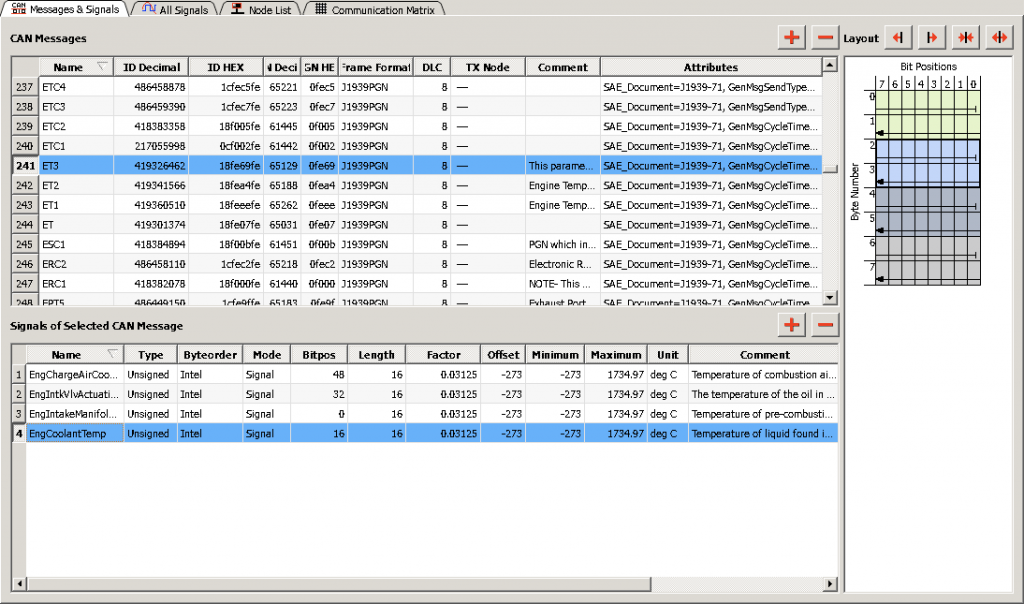
For this example, I’ll concentrate on only one signal within the data, the EngCoolantTemp signal. Here is a snip taken from the free Kvaser application, Kvaser Database Editor 3, available at the link above.

Screen Shot 2019-09-16 at 3.51.38 PM

What this data tells me is that the signal EngCoolantTemp is an unsigned integer of the Intel format, starts at bit position 16 and is 16 bits long. It also tells me that the offset is -273 and the scaling factor for the signal is 0.03125.

We can now manually do what CanKing does with the information in the DBC file, and the data in the signal EngCoolantTemp. First let’s isolate the signal. Here are the eight bytes of data transmitted in the message, with the signal EngCoolantTemp in the red box below:

Eight bytes of CAN data transmitted in the message, with the signal EngCoolantTemp in the red

How do we know where the signal EngCoolantTemp is within the message? The DBC file tells us that the signal starts at bit position 16 and is 16 bits long. If we read the data from left to right, we see 9C in the first 8-bit positions (bits 0 through 7), 27 is the second byte in the message (bits 8 through 15), and DC 29 are in bit positions 16 through 31.  Bits 16 through 31 represent what we know is the 16-bit value of EngCoolantTemp.

Before we can apply the offset and scaling factor, we must worry about byte order. This is where Byteorder Intel comes into it; the Intel format for byte order is referred to as Little-end-in, or least significant byte first. If the least significant byte is transmitted first, we must reverse the two bytes of the signal and the signal is going to be 29DC. This is the hexadecimal value as transmitted for the signal EngCoolantTemp, before offset and scaling are applied.

Next, we must convert the value to decimal, and we can do this with a hand calculation, or with the calculator on our computer, set in Programmer mode:

29DC (base 16) = 10,716

(If this conversion is not second nature to you, please go back and review numbering systems with different bases, and HEX to decimal conversions.)

Now we’re ready to apply the scale and offset. Both the scale and offset are shown as a decimal number so we apply them to the decimal value we have for EngCoolantTemp, 10,716:

First we apply the scale:

10,716 x 0.03125 = 334.875

Next, applying the offset gives us this:

334.875 – 273 = 61.875

The units on this signal are in dec C so the answer is 61.875 deg C just as shown in the above snip from CanKing.

 As you can see, if you look back at the value for EngCoolantTemp above, as interpreted by CanKing, it is the exact value we’ve calculated here. What we’ve manually done here is the exact same calculation done by any software application that uses a DBC file to display data in a human readable format. We’ve taken the raw data received through a CAN bus interface, as it was received from the bus, and applied the definitions and information within the appropriate DBC file, and offset and scaled the raw data to get a human readable value. Without the information in the DBC file the CAN data is useless and without meaning. It is therefore concluded that the DBC file is the most common way of communicating critical information about the identification and the data communicated on a CAN bus.

Questions?

Feel free to contact us at support@kvaser.com, or Bryan directly at bryan.hennessy@kvaser.com.

Additional Training

Additional training, including on-site training, is available from Kvaser’s qualified technical partners:

Author Image

Bryan Hennessy

Bryan Hennessy is the Technical Partner Manager for Kvaser AB, with a background in J1939, CAN diagnostics, marine electronics, and semiconductors.