This Developer Blog is the second of a 3-part series taking a look at SAE J2534. This series introduces SAE J2534 (including it’s multiple editions), describes how to use the 2004 API, and then provides instruction on getting started with Kvaser and J2534.
Developer Blog
SAE J2534 (Part II): Using the 2004 API
2 Using the 2004 API
To use the J2534 API productively, you need both an understanding of the protocol you want to use and the API’s sequence of operations for that protocol — this is despite J2534’s efforts to be protocol-agnostic. Let’s start with a brief overview of the CAN-based protocols supported (as of J2534-2 2019), and then quickly go over how you would use each one through the J2534 API.
2.1 Protocol Basics
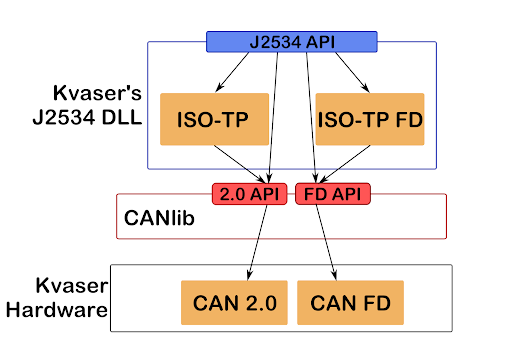
We’ll be going through the four protocols currently supported by Kvaser’s J2534 DLL: CAN 2.0, CAN FD, ISO-TP, and ISO-TP FD. In J2534 they have separate protocol “ID”s and we will treat them as separate protocols, but of course the truth is slightly more nuanced. The two FD-protocols are really updated versions of the non-FD versions that support the CAN Flexible Data Rate Format, still providing all the functionality of their non-FD versions. It is also worth mentioning that ISO-TP (with or without FD) is a higher-level protocol that exists on top of CAN (correspondingly 2.0 or FD).

2.1.1 CAN 2.0
The basis of all following protocols, CAN 2.0 (sometimes called Classic CAN) is a fault-tolerant protocol for broadcasting messages, called Frames, for all nodes on the bus to see. Frames consist of CAN Data (up to 8 bytes in length) and a CAN ID that can be either 11 (standard) or 29 (extended) bits long, and is used to prioritize which frames are let onto the bus first — known as “arbitration”. These frames are then sent on the bus at a predefined bitrate.
2.1.2 CAN FD
In 2015 the standards document for CAN, ISO11898, was updated to include CAN FD; CAN with a Flexible Data rate. This means that you can now, optionally, use one bitrate for the arbitration of CAN IDs and another (higher one) for sending the actual data. And to make use of the higher transmit speeds we can also send much larger frames, with CAN Data lengths of 12, 16, 20, 24, 32, 48, and 64 bytes – in addition to the up to eight bytes already allowed by CAN 2.0.
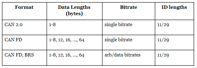
On the bus, the decision to use bitrate switching, BRS, is encoded per frame in one of the transmitted bits. The overall decision of whether to use CAN 2.0 or CAN FD is also encoded in one of the transmitted bits (though you can’t use BRS if you don’t also use FD), meaning devices that support CAN FD can read and write messages in three different formats:

Though note that we can still choose whether we want 11 bit or 29 bit IDs regardless of format. The two bitrates used with BRS are usually called “Arbitration Bitrate” and “Data Bitrate” (maybe throwing a “-Phase” into the middle as well).
2.1.3 ISO-TP
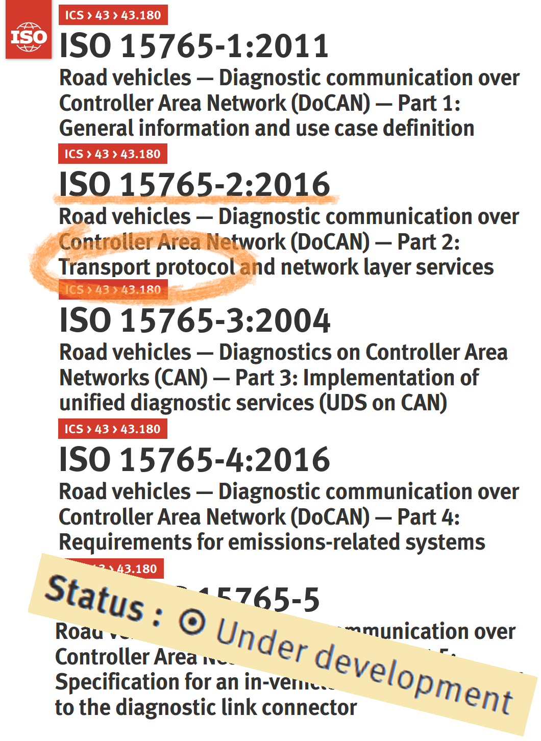
ISO 15765 is a family of standards by the International Standards Organization. We’re interested in the second part, ISO 15765-2, which defines a “Transport protocol and network layer services” — specifically we need to know about the transport protocol, ISO-TP.
Note that this protocol is given various different names by different people, as it is never named in the standard itself. J2534 calls it ISO 15765 (despite there being four other standards in the ISO 15765 family), others call it ISO 15765-2 (despite that standard standardizing a lot more than just the transport protocol), but I will continue to call it ISO-TP (ISO Transport Protocol) as that is the most unambiguous term I have found, referring to the transport protocol and the transport protocol only.
Now take a deep breath, we haven’t actually started on how ISO-TP works. ISO-TP is a higher-level protocol built on top of CAN 2.0, whose main purpose is to allow messages to be “segmented”, split over multiple CAN frames — which means you can send much longer messages. To do so in an orderly fashion, it uses a back-and-forth between the sender and the receiver to control how quickly frames should be sent and make sure they arrive.
This back-and-forth means that, if you want your message to be segmented, it has to be sent to a sole receiver. This is the final part of ISO-TP; messages can either be sent one-to-one or one-to-many. In ISO-TP parlance, one-to-one communication is called “physical addressing” and one-to-many is called “functional addressing”. Although if you are not used to addressing in vehicles those names are more confusing than helpful.

Segmentation
So you want to send an ISO-TP message? Well, if it fits in a single CAN frame then all is well and it is transmitted directly as a Single Frame (SF). For one-to-many communication, this is the only allowed method — one-to-many ISO-TP messages must fit into a SF.
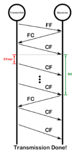
But for one-to-one communication it’s okay to send longer messages. In that case, the transmitter sends a single CAN frame with as much payload as can fit, a First Frame (FF), and then a (single) receiver must be set up to reply with a Flow Control (FC) frame. This can pause, cancel, or continue the transmission, and in the case of continuing it contains two parameters that will be in use until the next FC: called STmin (Separation Time MINimum) and BS (Block Size).
The transmitter will then send one “block” of CAN frames containing payload, called Consecutive Frames (CFs), and the number of such frames sent is controlled by Block Size. The Separation Time Minimum is the amount of time that must pass between CAN frames being sent on the bus. After a block is transmitted, the transmitter waits for another FC and then repeats. When the entire payload has been transmitted, the conversation quietly stops.

Addressing
Each node in the network has an address, and for each message this is compiled into “Address Information” in one of several different ways, some standardized and some not, each with several different variations and done differently depending on its functional or physical addressing.
Fortunately for me, the J2534 API leaves this all up to the user. As far as the API is concerned, each ISO-TP message has an address. This can either be an “extended” address, in which case it is one byte longer than the CAN ID, or just a normal one in which case it is exactly equivalent to the CAN ID.
It is then up to the user to define:
- Which addresses to accept SFs from.
- Which addresses to listen to segmented transmissions on, and which addresses to reply to each with.
- Which addresses can be transmitted on, and which addresses to expect replies from for each.
2.1.4 ISO-TP FD
The 2016 version of ISO 15765-2 added support for using CAN FD frames underneath ISO-TP. Fortunately for us, this doesn’t change much. You must now specify if you want the frames to be CAN 2.0, CAN FD, or CAN FD with BRS as well as specifying how large you want the individual CAN FD frames to be (you might not want every frame to be 64 byte long).
The other difference is that ISO-TP messages can have a payload of at most 4095 bytes, while ISO-TP FD added new mechanisms that allow for four gigabytes (4294967296 bytes).
…of which the J2534 API can only utilize 28 or 29 extra bytes, for a total of 4124 or 4123 depending on whether we’re using extended addressing. This is because messages are put in a struct with a static size. :/. (Because of this, the Kvaser API doesn’t currently implement that extra machinery.)
2.2 Sequence of Operation
So now that you’re up to date with your favorite protocol, how do you go about setting up the DLL for communication? Well the basic call sequence is:
- PassThruOpen(): Open a device (Kvaser DLL only has one device).
- PassThruConnect(): Connect a channel on the device, using a particular protocol ID.
- Use the channel however you want
- PassThruDisconnect(): Disconnect the channel
- PassThruClose(): Close the device.
The first step is to open a device and the second step is to use that device to connect to a channel. The base J2534-1 2004 only has a single device, but you must still open it in order to connect to a channel. If the DLL implements access to additional channels per J2534-2, you can connect to several channels using the same device, as long as they don’t use the same physical connection.
As disconnecting the channel and closing the device is not very interesting, those steps will be omitted from now on.
Note that all API calls return a status and if everything is fine that status will be STATUS_NOERROR = 0. Otherwise, call PassThruGetLastError() to get a more detailed description of what went wrong e.g. whether the CAN ID you supplied was too small or large, or if it was the CAN data that was wrong instead of just ERR_INVALID_MSG.
2.2.1 CAN 2.0
Protocol IDs: CAN, CAN_CH1, CAN_CH2…
CAN uses the channel number supplied in registry, CAN_CH1 is CANlib channel 0, CAN_CH2 is CANlib channel 1, etc.
- PassThruOpen()
- PassThruConnect(), selecting CANlib-channel using the protocol ID and giving the bitrate. In the connect flags you must specify whether you want the channel to be able to send frames with 11 or 29 bit CAN IDs, or both.
- Messages can be sent without any setup.
- PassThruStartFilter(), defining which CAN IDs should be listened to and be reported to the user. Before setting a filter, no traffic from the bus can be seen.
2.2.2 CAN FD
Protocol IDs: FD_CAN_CH1, FD_CAN_CH2…
CAN FD cannot use the channel number from registry, the CHx IDs work like with CAN 2.0: FD_CAN_CH1 is CANlib channel 0, FD_CAN_CH2 is CANlib channel 1, etc.
- PassThruOpen()
- PassThruConnect(), selecting CANlib-channel using the protocol ID and giving the arbitration bitrate (only). In the connect flags you must specify whether you want the channel to be able to send frames with 11 or 29 bit CAN IDs, or both. Channel is not connected yet.
- PassThruIoctl(), SET_CONFIG: FD_CAN_DATA_PHASE_RATE to desired data bitrate. Channel is now connected to the CAN bus.
- Messages can be sent without any setup.
- PassThruStartFilter(), defining which CAN IDs should be listened to and be reported to the user. Before setting a filter, no traffic from the bus can be seen.
Even if you never use bitrate switching, you must specify the data bitrate before the channel will connect to the CAN bus and let you send and receive messages.
2.2.3 ISO-TP
Protocol IDs: ISO15765, ISO15765_CH1, ISO15765_CH2…
Similarly to CAN 2.0, ISO15765 uses the channel number supplied in registry, ISO15765_CH1 is CANlib channel 0, ISO15765_CH2 is CANlib channel 1, etc.
- PassThruOpen()
- PassThruConnect(), selecting CANlib-channel using the protocol ID and giving the bitrate. In the connect flags you must specify whether you want the channel to be able to send frames with 11 or 29 bit CAN IDs, or both.
- Non-segmented messages can be sent without any setup.
- PassThruStartFilter(), defining pairs of message addresses. The channel will respond to messages that have the reception address using the transmission address for the FCs. Segmented messages can also be sent on the transmission address, in which case the channel will expect FCs with the reception address. For receiving one-to-many (physically addressed) messages, supply the same address twice (as one-to-many messages never need FCs).
2.2.4 ISO-TP FD
Protocol IDs: FD_ISO15765_CH1, FD_ISO15765_CH2…
Similarly to CAN FD the channel number from registry cannot be used while FD_ISO15765_CH1 is CANlib channel 0, FD_ISO15765_CH2 is CANlib channel 1, etc.
- PassThruOpen()
- PassThruConnect(), selecting CANlib-channel using the protocol ID and giving the bitrate. In the connect flags you must specify whether you want the channel to be able to send frames with 11 or 29 bit CAN IDs, or both. Channel is not connected yet.
- PassThruIoctl(), SET_CONFIG: FD_CAN_DATA_PHASE_RATE to desired data bitrate. Channel is now connected to the CAN bus.
- Non-segmented messages can be sent without any setup.
- PassThruStartFilter(), defining pairs of message addresses. The channel will respond to messages that have the reception address using the transmission address for the FCs. Segmented messages can also be sent on the transmission address, in which case the channel will expect FCs with the reception address. For receiving one-to-many (physically addressed) messages, supply the same address twice (as one-to-many messages never need FCs).
Definitions
- ISO-TP
The Transport Protocol defined in 15765-2:2011, without the support for CAN FD which was introduced in 15765-2:2016. Sometimes ambiguously called simply ISO 15765-2 or ISO 15765.\ - ISO-TP FD
The Transport Protocol defined in 15765-2:2016 (including the support for CAN FD).
CAN
The Controller Area Network as described in ISO 11898, a blanket term for both CAN 2.0 and CAN FD. - CAN 2.0
The “classic” CAN with up to eight bytes of data and no support for bit rate switching. - CAN FD
CAN Flexible Data rate protocol that supports longer data than CAN 2.0 as well as bit rate switching. - J2534
A family of standards that specify the Pass-Thru device and the Pass-Thru API used to communicate to the device via a J2534 DLL. - J2534 DLL
The DLL provided by an interface manufacturer, which conforms to the Pass-Thru API. - Pass-Thru API
The API of all J2534 DLLs, which the vehicle manufacturer can use regardless of which company’s J2534 DLL is actually in use. - Pass-Thru device
A specific type of device standardized by J2534, which has an accompanying J2534 DLL.
