CAN Oscilloscope Pictures
Here’s a picture from a perfectly normal ISO 11898 CAN bus, running at 1 Mbit/s. The transceiver is a 82C251; in other words, the physical layer is the one specified by ISO 11898.
The measurement was done between CAN_H and GND. Note that the quiescent and recessive bus voltages lie around 2.5 V. When a dominant bit is transmitted the voltage rises to around 3.5V.
Now here’s the same bus, but measurement is done between CAN_L and GND instead:
Here’s another message, sent at 125 kbit/s. The message’s (11-bit) identifier is 300, or 12c in hexadecimal. Look closely and you should be able to identify the first bits in the message.
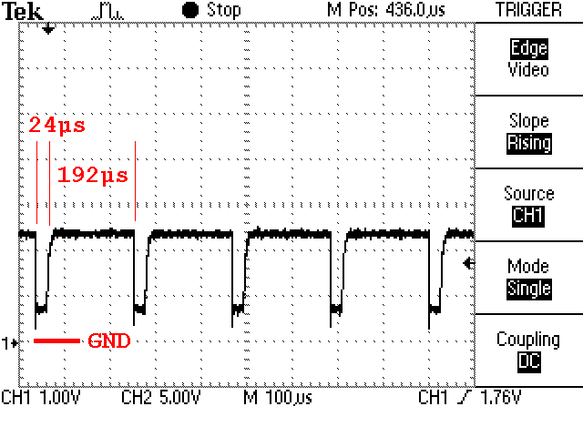
Here’s a trickier picture. It shows the same message as above, still (11-bit) identifier 300 and still 125 kbit/s, but without termination on the CAN bus. The CAN cable was a short run of flat ribbon cable.
So, what’s happening? This is 125 kbit/s, so one bit is 8 microseconds.
- First the transmitter sends a start bit. This is a logical ’0′, i.e. a dominant level.
- Then the identifier is transmitted. 300 decimal is 12c in hex, or 001 0010 1100 in binary. The first two zeroes are transmitted just fine. – This explains the 24 microseconds of dominant level as seen in the picture.
- Then a ’1′ should be transmitted, but as the bus isn’t terminated the rising slope is not what it should have been. The transmitting node will now think it saw a ’0′ on the bus.
- Since this happens during the arbitration phase, the transmitter will stop transmit – it thinks that some other node is transmitting. The bus will now be left recessive, because no-one is in fact transmitting.
- After 6 recessive bits, both the transmitter and the receivers will detect a stuff error and the error handling starts. At this point, 80 microseconds has gone (one start bit, two ’0′, one misinterpreted bit, and six recessive bits – a total of 10 bits = 80 microseconds.)
- All nodes detecting the stuff error will now start to transmit an error frame. In this case the error frame is passive because a number of errors were generated before the above picture was captured, so the transmitter is error passive. A passive error frame is just as an active error frame, but it’s transmitted with a recessive level and so isn’t visible on the bus.
- The passive error frame prevails for 6 bit times.
- Then all nodes are waiting for a period of 8 recessive bits, called the error delimiter.
- Then all nodes are waiting for a period of 3 recessive bits, called the intermission.
- Summing up the numbers above, we arrive at 1+6+6+8+3 = 24 recessive bits = 192 microseconds (see the picture!)
Moral: Always terminate the CAN bus! The reflections will not necessarily hurt, but the bad shape of the edges will kill the communication.
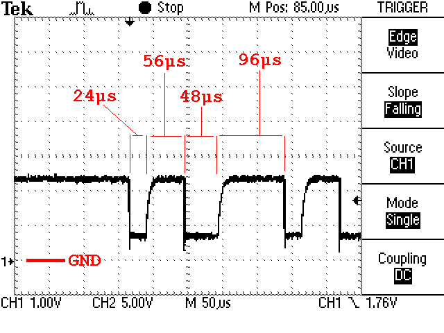
Here’s the same CAN bus in another time scale:
The CAN bus was around 2 decimeters (8 in.) long. The undershoot and ringing is visible but in this case clearly not important. This time the slow rising edge is the culprit.
Here’s the same setup, but this time both the transmitter and the receiver are error active:
What’s happening?
- Just as in the figure above, three ’0′ are transmitted (takes 24 microseconds,) and the next bit is misinterpreted so the transmitter thinks it has lost the arbitration.
- The transmitter waits for 6 bits and then detects a stuff error. The misinterpreted bit and the 6 bits takes 56 microseconds.
- The transmitter and the receiver now start to transmit an error frame. It’s 6 dominant bits (48 microseconds.)
- The nodes that transmitted the error frame now waits for 8 recessive bits but as the rising slope is bad, the first bit is misinterpreted. The nodes will think this is another node transmitting an error frame and will ignore it.
- When the bus is back at the recessive level all nodes wait for 8 bits.
- Then the intermission of 3 recessive bits comes.
- 3+9 = 12 bits = 96 microseconds, as seen in the picture.
- Then the transmitter tries again with the same result. After a while the transmitter goes error passive and will behave as described earlier.
Here is yet another picture. In this setup there is only a single node on the (properly terminated) CAN bus. It’s trying to transmit a message, but no one is listening.
So what’s happening?
- First, the transmitter sends the whole message.
- The transmitter expects a dominant level in the ACK slot, but as no one is listening, no ACK arrives, so the transmitter detects an Acknowledgement error.
- The transmitter then transmits a passive error flag (passive because in the picture above it has been trying to send for a few seconds, so it’s no longer error active.)
- The passive error flag is followed by an error delimiter and the intermission.
- Since this node tried to send a message but failed, it has to wait for another 8 bits before initiating a new transmission. This is called ‘suspend transmission’ in the CAN spec.
- The transmitting node also has to increase its tx error counter by 8, but by a special case in the CAN spec, this happens only as long as the transmitter is error active. When the transmitter goes error passive it will not (in this case) increase its tx error counter, and consequently the transmission is retried forever.
So what you see in the picture above is a message being transmitted, followed by a small pause which is the sum of the error flag, the error delimiter, the intermission and the suspend transmission. The message is then retransmitted and retransmitted and…


